DLXview
(Preliminary) User's Manual
 Introduction
-
DLXview History and Future
-
Contact Us
-
Getting Started
-
...the Simple Way
-
...the Advanced Way
-
Control Panel
-
Configure
-
Step Forward
-
Next Cycle
-
Go
-
Step Back
-
Previous Cycle
-
Reset
-
Trace
-
Quit
-
Pipeline Modes
-
Basic Pipeline
-
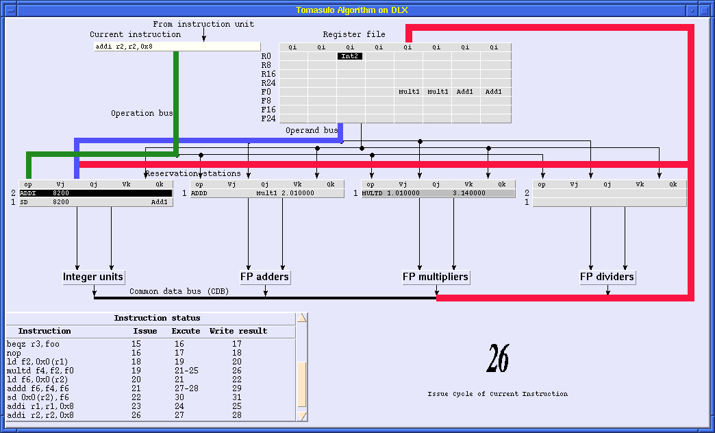
Tomosulo Algorithm
-
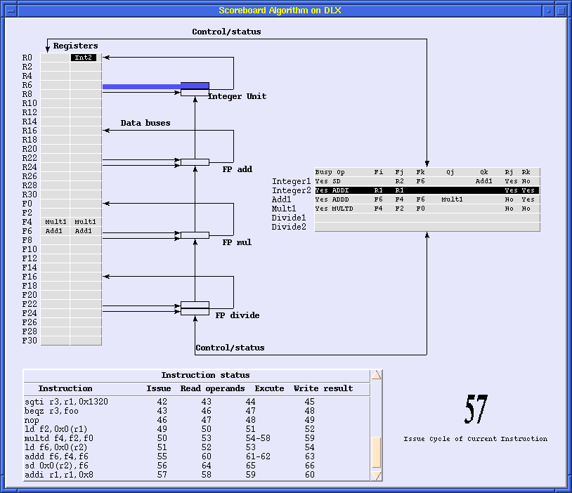
Scoreboarding
-
Appendix
-
Format of a Startup File
-
A Sample Startup File
-
Formats of Code and Data Files
-
Format of Register Initialization File
-
Sample Input Files
-
DLXview History and Future
-
Contact Us
DLXview is an interactive pipelined computer simulator using the
DLX instruction
set described in
Computer Architecture: A Quantitative Approach (CA:AQA)
by John Hennessy and David Patterson. The main goal of dlxview is
to provide a
graphical environment where the internal operations of a processor are
much easier to understand than their text description only. In addition
to its pedagogical purpose, dlxview also serves to be a handy tool in DLX
instruction set understanding, debugging, and in processor performance
evaluation.
DLXview was created by modifing and extending DLXsim,
a generic, non-graphical
DLX pipeline simulator, which was in turn modified from a MIPS simulator.
This is not surprising given the similarities between the DLX and MIPS
instruction sets. The simple pipelining model in DLXsim has been
greatly enhanced to support the execution models of basic
pipelining, scoreboarding,
and the Tomasulo algorithm. The graphical interface built on top of Tcl/Tk
tries to expose as much nitty-gritty detail as possible as explained by the
CA:AQA textbook on a cycle-by-cycle basis.
The current version of dlxview is a branch of the on-going
CASLE
(Compiler/Architecture Simulation for Learning and Experimenting)
project at
Purdue University's
School of Electrical and Computer
Engineering, which aims to provide a comprehensive
pedagogical tool for learning architectural concepts, compiler
technologies, and the interactions between them. Based on the experience
in the course of developing dlxview,
we plan to build a more powerful simulator
which will cover the general microparallel execution models such as
superscalar and VLIW with differing configurations. This future tool
will also target some popular commercial RISC processors, such as the
Alpha and PowerPC series.
DLXview is a project in progress. The latest news about dlxview
may be found at the
dlxview homepage.
For project suggestions, bug reports and further information, please contact
George Adams
at
gba@ecn.purdue.edu.
Return to Contents
-
...the Simple Way
-
...the Advanced Way
Be sure the "dlxview" executable is in your path, and simply type
dlxview
followed by the ENTER or RETURN key to invoke
dlxview to bring up the initial dlxview simulator window.
Additional startup files can be used to save the time of a series of
interactive configuration steps. Suppose the startup file is called
"foo"; there are two ways of having dlxview read it.
- Invoke dlxview by passing the startup file as a command line option:
dlxview -f foo
followed by the ENTER or RETURN key.
The disadvantage of this approach is that the
input terminal will no longer accept other key strokes during the
simulation session. Fortunately, this feature is irrelevant to most
users who do not require extensive debugging of DLX assembly programs
and dlxview internals.
- Start a dlxview session first by typing
dlxview
followed by the ENTER or RETURN
key at the command line, and type
source foo
followed by the ENTER or RETURN key
after the (dlxview) prompt in the command line window.
Return to Contents
-
Configure
-
Step Forward
-
Next Cycle
-
Go
-
Step Back
-
Previous Cycle
-
Reset
-
Trace
-
Quit
In dlxview,
if a button is enabled, the button text is black; if it is disabled, the
button text is gray. This section explains the basic operations of the
control panel window buttons.
When dlxview is invoked without using a startup file, or right after the
processor
state is reset, this button must be pressed to configure the machine to be
simulated. In the mode configuration window,
there are three radio
buttons on top. Click on the button corresponding to the mode to be
simulated and another larger parameter configuration window will
appear corresponding to either the basic
pipeline,
scoreboard, or
Tomasulo
scheduling modes. Configure the machine by dragging the sliders and
clicking the radio buttons. Then exit the configuration windows by
pressing the "Ok" button in the parameter configuration window, and
then pressing the "Ok" button in the mode configuration window.
In the middle of a simulation session, the "configure" button in the control
panel can be pressed again to check the current configurations. However,
the sliders and buttons on the configuration windows are disabled; i.e.,
the processor configuration cannot be changed once simulation has started. To
abort the current configuration, press the "reset" button on the control
panel first, and then configure the machine from there.
Note that in the CA:AQA text, the latency of a functional unit
is defined as the number of intervening cycles between an instruction that
produces a result and an instruction that uses the result (see
CA:AQA,
page 189). For example, the integer unit will have latency 0,
which is somewhat
unintuitive. In dlxview, he latency of a functional unit is defined as
the total number of clock cycles an instruction will stay in this
functional unit.
Therefore, the latency is one clock cycle more than specified in CA:AQA.
For more information on the configurable parameters, please refer to
tables in the
Appendix.
The processor must be configured before loading a file. A file
selection window will pop up after pressing the "load"
button. DLXview accepts three types of files before a simulation session
begins. The *.s files are assembly code file, *.d files are data
file. It is not necessary to have a separate data file. Code and
data files can be merged into a single *.s file.
*.i files contain
commands to initialize the registers to be used. It is possible to add
a few instructions in the assembly code to do the same job, the catch
is that the code segment won't start at clock
cycle one. Register initialization is unavoidable in some
situations, such as examining the execution of a loop
in which some instructions have pre-specified operands.
Letting this loop start at clock cycle one, as most of the examples
and exercises in the CA:AQA text do, will make it easier to focus on the
loop instructions themselves without worrying about other minor details
such as the dependence between a loop instruction in the first
iteration of a loop and an instruction outside the loop. It is much
handier to write a separate register initialization file for these
cases.
See also
-
Formats of Code and Data Files
-
Format of Register Initialization File
-
Sample Input Files
When loading related input files, clicking
the left mouse button on the file selection window for any one of the
related files will highlight these files as a group,
if the related files have the same base name. Press the "load" button
in the "Load" window to load these files. When choosing to load a
single file, the contents of the selected file will appear to the right
of the file selection window.
You can load as many files as you wish and switch
between related and single load modes. When all the files
are loaded, press the "Done" button to close the "Load" window. Note that
pressing "Done" directly without pressing "Load" first will result in
no file being loaded.
The "edit" button can be invoked any time during a simulation session to
revise the current DLX code and edit the input files. When the edit window
pops up, the assembly code executed by the current simulation session will
be automatically copied into the edit window. If a totally new
assembly file is going to be edited, simply press the "Clean" button
in the edit window to get rid of the old files. When editing is completed,
the new file can be directly loaded into dlxview to start another simulation
session by pressing the "Load" button in the edit window. Before the new
file is actually loaded, a dialog box will ask if any other data file
needs to be loaded first. If the answer is "No", then the *.d file used in the
current simulation session will be loaded first by default. Once a newly
edited file has been loaded into the simulator through the edit window,
the current simulation session is interrupted, and the processor is
reset in order to run the latest loaded file. With the help of the code editor,
you can change the assembly code being executed at any time and try the
new simulation without leaving the dlxview environment.
If no instruction has entered the pipeline yet,
pressing "step forward" will pop up a window to allow entering the
starting address. Otherwise, the simulation will continue from
wherever execution previously stopped and execute the next instruction. The
clock cycle will always advance to the first stage of the newly processed
instruction.
If no instruction has entered the pipeline yet,
pressing "next cycle" will pop up a window to allow entering the starting
address. Otherwise, the simulation will advance by one clock cycle.
The simulator will not necessarily proceed to the next instruction, because
of pipeline stalls. Pressing "next cycle" continuously will
show every detail in the simulated pipeline.
If no instruction has entered the pipeline yet,
pressing "go" will pop up a window to allow entering the starting address.
Otherwise, the simulation will continue from wherever execution
previously stopped and will not stop until the execution terminates
naturally. Do not forget to put a trap #0 instruction at the end of
the assembly code; otherwise, the simulator will continuously fetch
new nop instructions from the zeroed memory locations proceding the input
code.
This button provides the flexibility to back step one instruction and
view the state of the processor at the clock cycle when the last instruction
entered the pipeline. If more than 1K clock cycles have already been
simulated, it will take a little while to move the pipeline to an earlier
state. Be patient!
The button provides the flexibility to wrap back the state of
the processor one clock cycle. If more than 1K clock cycles have
already been simulated, it will take a little while to move the pipeline
to an earlier state. Be patient!
The "reset" button allows changing the pipelining mode, the configuration of
the processor, or the input code.
The "trace" button provides the capability to output an instruction trace
or memory reference trace. This may be fed into a trace-driven simulator
or the dinero cache simulator later to do further analysis.
Enter the file name
to save the trace as. The trace will be collected starting from
the current instruction. Normally, the trace file is not available until
the current simulation session ends; i.e, the simulation stops naturally or
is interrupted by a reset. However, when pressing either the "step back"
or "previous cycle" buttons during the simulation, the tracing process is
stopped automatically to avoid producing garbage wrapped around trace.
In this case, a trace file containing the information from where
tracing started to the last instruction will be generated.
Terminates the dlxview session.
Return to Contents
-
Basic Pipeline
-
Tomosulo Algorithm
-
Scoreboarding
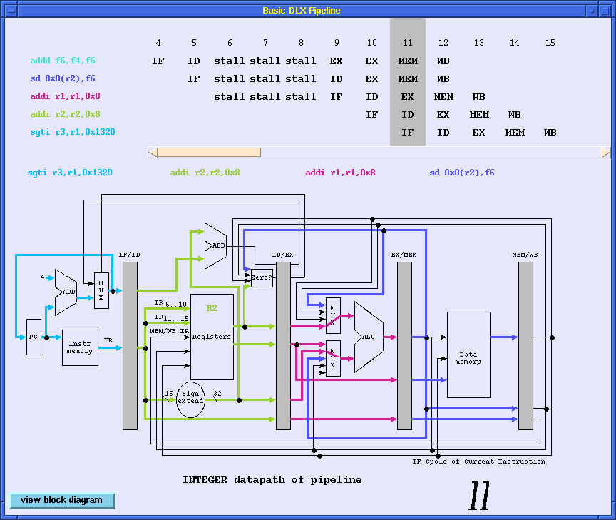
In the visualization window for the basic
pipeline, the top half is an instruction and clock cycle table, and the
bottom half can be switched between the block diagram of the DLX
pipeline (see Figure 3.44 in the CA:AQA text) and the datapath of the
integer unit (see Figure 3.22 in the CA:AQA text). Each instruction
entering the pipeline is assigned a unique color. Instructions of a
particular color listed in the top half of the window
execute in the pipeline stage corresponding to same color.
The window exhibits the pipeline state for one particular clock cycle. This
clock cycle number is displayed at the lower-right corner of the
visualization window, and is highlighted by a gray strip in the clock
cycle table.
The instruction and clock cycle table are capable of displaying the latest
five instructions simulated by dlxview, with the last row showing the
last instruction entering the pipeline. The highlighted gray
strip identifies which instruction is in which pipeline stage.
There might be more than five instructions in the pipeline at
any time time; the earlier instructions are wrapped off in this
table. To determine exactly how many instructions are in the
pipeline, count the number of colored boxes in the bottom
pipeline visualization.
In the pipeline block diagram, if a floating point functional unit is
fully pipelined, the EX pipe stages for this functional unit will be
drawn as separated boxes. On the other hand, the multicycle EX stage
of a unpipelined floating point unit is shown as a long box with
internal lines. The block diagram as a whole is also convenient for
determining which instruction is in which pipeline stage. For a
pipeline that supports multiple outstanding FP operations, there might
be multiple instructions entering the MEM or WB stage simultaneously.
(It can be proved that for the particular DLX machine described in the
section 3.7 of the CA:AQA text, at most two
instructions will go to the MEM or WB stages at the same time. This is left
as an exercise for the reader.)
In this case, multiple colors will occupy the MEM and WB boxes
(they should be split in a real implementation).
The integer datapath
shows what is happening in the integer datapath. Nevertheless,
floating point operations are exhibited here also when they are in the
IF and ID stages. At a particular clock cycle, there might be some
floating point instruction executing or writing their results back
to the register file; they may not appear in the integer datapath.
When a mux is used for selecting operands, the line connecting the
output and the selected input indicates where the operand came
from. For example, by examining the input muxes to the ALU, you can
determine whether operands came from the register file, the forwarding
path, or the immediate operand stored in the ID/EX stage-register. If
an operand is forwarded, it is also easy to trace back to the forwarding source
from the highlighted wires.
The following is a brief description of the features of the DLX
pipeline defined in the CA:AQA text that are supported by dlxview.
- Instructions are fetched and decoded sequentially.
- Multiple floating point functional units, either fully pipelined or not,
can be configured for the processor. However, only one integer unit
is allowed.
- Branches are resolved at the ID stage. There is one branch delay slot
after the branch instruction, and branch penalties are reduced by the
delayed-branch scheme. It is up to the compiler or user, whichever
provides the DLX code, to make sure the successor instruction of a branch
is valid and useful. If no useful instructions can be found, a nop
instruction should be inserted after the branch in the assembly code.
- There is only one write port to the FP register file.
- Four types of hazards are checked for in the ID stage:
- Structural hazards,
- WAR hazards,
- WAW hazards, and
- FP register file write port conflicts.
Moving branch handling logic from the MEM stage to the ID stage may
cause additional stalls in the pipeline because of data dependences.
Since this hazard is not dlxviewussed in the CA:AQA text,
the dlxview implementation is briefly explained here.
The hazard may be viewed by writing a
proper code sequence and testing it with dlxview.
- If the operand of a branch is generated by the preceding
integer ALU instruction, the pipeline will stall for one cycle. After
that, the operand is forwarded from the EX/MEM stage. The stall
might last longer for FP branches in this case, depending on the latency
of FP instruction.
- If the operand of a branch is generated by the preceding
load instruction, the pipeline will stall for two cycles. After
that, the operand is forwarded from the MEM/WB stage.
- If the operand of a branch is generated by the
load instruction preceding the instruction which precedes the branch
instruction, the pipeline will stall for one cycle. After
that, the operand is forwarded from the MEM/WB stage-register.
visualization window
visualization window
Return to Contents
-
Format of a Startup File
-
A Sample Startup File
-
Formats of Code and Data Files
-
Format of Register Initialization File
-
Sample Input Files
The startup file contains a sequence of parameter assignments. Each
assignment is a variable-value pair with the following Tcl syntax:
varName ?value?
If there is more than one item in a value (for example, multiple
assembly code files and data files are required to be loaded before
execution) then these items should be wrapped by a pair of double
quotes or curly parenthesis. There is no ordering of assignments;
however, the end of assignments should be followed by a
Start
command. The configurable variables are listed in
Table 1.
All the variables and commands are case sensitive: make sure
to type them correctly. Some variables are only meaningful in
certain pipelining modes;
Table 1
gives the applicable mode to each
variable in the last column. Unpredictable results or core dumps
will appear if a variable is assigned under a wrong mode. A "must"
means the corresponding variable must be set no matter what pipelining mode has
been chosen. If a variable is not been specified in the startup file, it
will take the default value.
Table 2
gives the domain of each variable and their default values.
Table 1. Configurable Variables and Their Meanings
VARIABLE           MEANING			   PIPELINE MODE
pipeline_mode      pipelining mode                 must
input_files        code/data/initialize file name   must
start_address      start address in the code       BasicPipe,ScoreBoard,Tomasulo
numWords           memory size		           BasicPipe,ScoreBoard,Tomasulo
num_int_units      number of integer units         ScoreBoard,Tomasulo
num_add_units      number of FP adders             BasicPipe,ScoreBoard,Tomasulo
num_mul_units      number of FP multipliers        BasicPipe,ScoreBoard,Tomasulo
num_div_units      number of FP dividers           BasicPipe,ScoreBoard,Tomasulo
int_latency        integer unit latency            BasicPipe,ScoreBoard,Tomasulo
fp_add_latency     FP adder latency                BasicPipe,ScoreBoard,Tomasulo
fp_mul_latency     FP multiplier latency           BasicPipe,ScoreBoard,Tomasulo
fp_div_latency     FP divider latency              BasicPipe,ScoreBoard,Tomasulo
add_ful_pipe       FP adder fully pipelined?       BasicPipe
mul_ful_pipe       FP multiplier fully pipelined?  BasicPipe
div_ful_pipe       FP divider fully pipelined?     BasicPipe
num_load_bufs      number of load buffers          Tomasulo
num_store_bufs     number of store buffers         Tomasulo
load_buf_latency   load buffer latency             Tomasulo
store_buf_latency  store buffer latency            Tomasulo
Table 2. Domain and Default Values for Configurable Variables
VARIABLE           DOMAIN			   DEFAULT
pipeline_mode      BasicPipe,ScoreBoard,Tomasulo    none
input_files        files with .s .d .i extension   none
start_address      any legal address or symbol     0x1000
numWords           [1, 16384]                      16384
num_int_units      1                               1
num_add_units      [1, 8]                          2
num_mul_units      [1, 8]                          2
num_div_units      [0, 8]                          2
int_latency        [1, )                           1
fp_add_latency     [1, )                           2
fp_mul_latency     [1, )                           5
fp_div_latency     [1, )                           19
add_ful_pipe       0 for no, 1 for yes             1
mul_ful_pipe       0 for no, 1 for yes             1
div_ful_pipe       0 for no, 1 for yes             0
num_load_bufs      [0, 8]                          0
num_store_bufs     [0, 8]                          0
load_buf_latency   [1, )                           1
store_buf_latency  [1, )                           1
	set pipeline_mode BasicPipe
	set fp_add_latency 3
	set num_add_units 1
	set mul_ful_pipe 0
	set fp_mul_latency 10
	set num_div_units 1
	set num_mul_units 1
	set fp_div_latency 24
	set input_files {f347.i f347.d f347.s}
- Comments are started with a semicolon, and continue to the end of line.
- Constants can be entered either with or without a preceding number sign.
- The format of instructions and their operands are as shown in the
CA:AQA text.
- Labels are defined by a group of non-blank characters starting with
either a letter, an underscore, or a dollar sign,
and followed immediately
by a colon. They are associated with the address immediately
following the last block of information stored. This has the negative
effect that if code follows a label following a block of
data that does not end on a word boundary (multiple of 4), the label
will not point to the first instruction in the code, but instead to 1
to 3 bytes before (since the address is only rounded when it is
necessary to correctly align data). This is done so that if a label
is found in the middle of a data section, it will point to the start
of the next section of data without the data having to be aligned to a
word boundary. The work-around for this is to use the
.align
(see below)
directive before labels that will not not be aligned with the data
following them. Labels can be accessed anywhere else within that file,
and in files loaded after that if the label is declared as
.global
(see below).
- The text (code) is ended by a trap #0 instruction.
While the assembler is processing an assembly file, the data and instructions
it assembles are placed in memory based on either a text (code) or data
pointer. Which pointer is used is selected not by the type of information,
but by whether the most recent directive was
.data or .text. The program
initially loads into the text segment.
The assembler supports several directives which affect how it loads the DLX
memory. These should be entered in the place where you would normally place
the instruction and its arguments. The directives currently supported by
dlxview are:
- .align n
Cause the next higher address with the lower n bits
zeroed (the next closest address greater that or equal to the
current address that is a multiple of 2^n).
- .ascii "string1", "string2", ...
Store the strings listed on the line in memory as a list of
characters. The strings are not terminated by 0 byte.
- .asciiz string1", "string2", ...
similar to .ascii,
except each string is followed by a 0 byte (like C strings).
- .byte "byte1", "byte1", ...
Store the bytes listed on the line sequentially in memory.
- .data [address]
Cause the following code and data to be stored in the data area.
If an address was supplied, the data will be loaded starting at
that address, otherwise, the last value for the data pointer will
be used. If we were just reading code based on the text (code)
pointer, store that address so that we can continue form there
later (on a .text directive).
- .double "number1", "number2", ...
Store the numbers listed on the line sequentially in memory as
double precision floating point numbers.
- .float "number1", "number2", ...
Store the numbers listed on the line sequentially in memory as
single precision floating point numbers.
- .global label
Make the label available for reference by code found in files
loaded after this file.
- .space size
Move the current storage pointer forwarded by size bytes (to leave
some empty space in memory).
- .text [address]
Cause the following code and data to be stored in the text (code)
area. If the address was supplied, the data will be loaded starting
at that address, otherwise, the last value for the text pointer will
be used. If we were just reading code based on the data pointer
store that address so that we can continue form there later (on a
.data directive).
- .word "word1", "word1", ...
Store the words listed on the line sequentially in memory.
DLXview allows the user access to a few simple C library functions through
the use of the trap
operation. Currently supported functions are:
open () (trap #1),
close () (trap #2),
read () (trap #3),
write () (trap #4),
printf () (trap #5).
When the appropriate trap is invoked, the
first argument should be located in the word starting at the address in r14,
with the following arguments (as seen in a C statement calling the function)
in words above that (r14+4, r14+8, ...). The result from the function call
will be placed in r1 (this means there is currently no support for the
library functions that return floating point values). If a double precision
floating point value is to be passed to a library function, it will occupy
two adjacent words with the lower word the value of the even valued floating
point register, and the higher word containing the value of the odd valued
floating point register (f0 in 0r(14), f1 in 4(r14)).
Note: The dlxview file loader is completely inherited from DLXsim,
and this
help section is directly copied from the DLXsim User's Manual.
Two types of register initialization commands exist. The first type
is used to initialize integer registers, and the second type is used to
initialize floating point registers.
For register designators, any of
the names "r0" through "r31" and "f0" through "f31" may be used. The names
"$0" through "$31" may also be used (instead of "r0" through "r31"),
however, it is safer to use "r" instead of "$" to avoid the confusion with
Tcl variables. The name "pc" may be used to refer to the program counter.
- put reg number
Store number in the register given by reg. To store floating
point numbers (single or double precision), use the
fput command.
- fput reg number [precision]
Store number in the register given by reg. If precision is
d,
the number is stored a double precision floating point number (in
two words). If precision is
f,
or no precision is given,
the number is stored as a single precision floating point number.
f347.s
LL:ld      f2, 0(r1)
   multd   f4, f2, f0
   ld      f6, 0(r2)
   addd    f6, f4, f6
   sd      0(r2), f6
   addi    r1, r1, 8
   addi    r2, r2, 8
   sgti    r3, r1, done
   beqz    r3, LL
   nop
   trap    #0


f347.i
   put     r1      0x1000
   put     r2      0x2000
   fput    f0      3.14    d


f347.d
   .data   0x1000
   .double 1.00, 1.01, 1.02, 1.03, 1.04, 1.05, 1.06, 1.07, 1.08, 1.09
   .double 1.10, 1.11, 1.12, 1.13, 1.14, 1.15, 1.16, 1.17, 1.18, 1.19
   .double 1.20, 1.21, 1.22, 1.23, 1.24, 1.25, 1.26, 1.27, 1.28, 1.29
   .double 1.30, 1.31, 1.32, 1.33, 1.34, 1.35, 1.36, 1.37, 1.38, 1.39
   .double 1.40, 1.41, 1.42, 1.43, 1.44, 1.45, 1.46, 1.47, 1.48, 1.49
   .double 1.50, 1.51, 1.52, 1.53, 1.54, 1.55, 1.56, 1.57, 1.58, 1.59
   .double 1.60, 1.61, 1.62, 1.63, 1.64, 1.65, 1.66, 1.67, 1.68, 1.69
   .double 1.70, 1.71, 1.72, 1.73, 1.74, 1.75, 1.76, 1.77, 1.78, 1.79
   .double 1.80, 1.81, 1.82, 1.83, 1.84, 1.85, 1.86, 1.87, 1.88, 1.89
   .double 1.90, 1.91, 1.92, 1.93, 1.94, 1.95, 1.96, 1.97, 1.98, 1.99
   .global done
   done:    .double 0

   .data   0x2000
   .double 2.00, 2.01, 2.02, 2.03, 2.04, 2.05, 2.06, 2.07, 2.08, 2.09
   .double 2.10, 2.11, 2.12, 2.13, 2.14, 2.15, 2.16, 2.17, 2.18, 2.19
   .double 2.20, 2.21, 2.22, 2.23, 2.24, 2.25, 2.26, 2.27, 2.28, 2.29
   .double 2.30, 2.31, 2.32, 2.33, 2.34, 2.35, 2.36, 2.37, 2.38, 2.39
   .double 2.40, 2.41, 2.42, 2.43, 2.44, 2.45, 2.46, 2.47, 2.48, 2.49
   .double 2.50, 2.51, 2.52, 2.53, 2.54, 2.55, 2.56, 2.57, 2.58, 2.59
   .double 2.60, 2.61, 2.62, 2.63, 2.64, 2.65, 2.66, 2.67, 2.68, 2.69
   .double 2.70, 2.71, 2.72, 2.73, 2.74, 2.75, 2.76, 2.77, 2.78, 2.79
   .double 2.80, 2.81, 2.82, 2.83, 2.84, 2.85, 2.86, 2.87, 2.88, 2.89
   .double 2.90, 2.91, 2.92, 2.93, 2.94, 2.95, 2.96, 2.97, 2.98, 2.99
Return to Contents
gba@ecn.purdue.edu